

Fuel Tank Construction
|
|
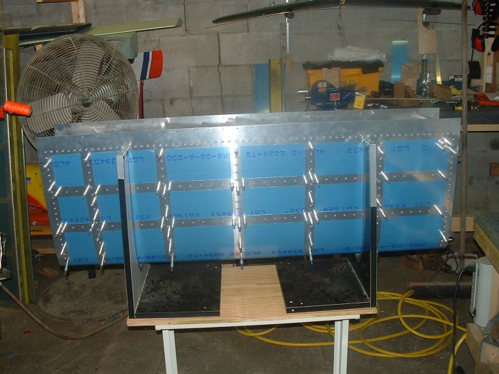
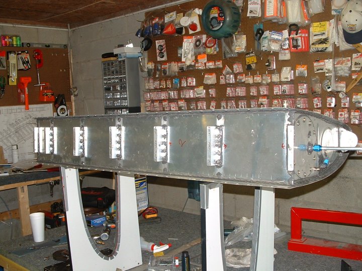
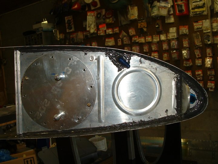
So the fun begins. Every since I started this project, I have read about how much of a pain the tanks were to construct. I have fretted over this but the time finally came. So far so good and it's actually been fun.....................but then I haven't started with the proseal!! Here is the bottom view sitting in the jig all clecoed together. | ||
|
|
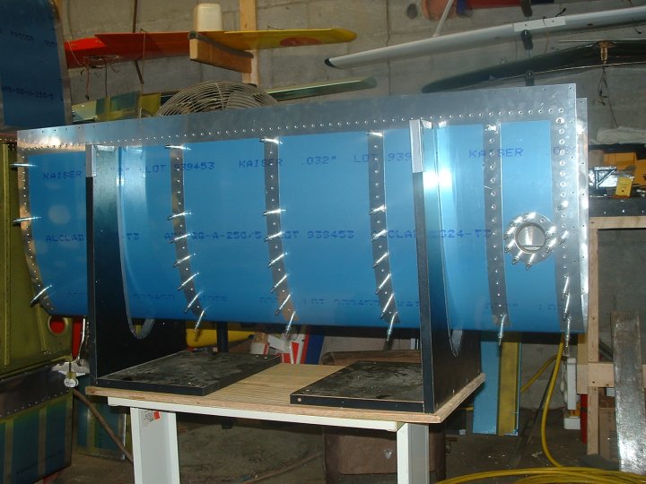
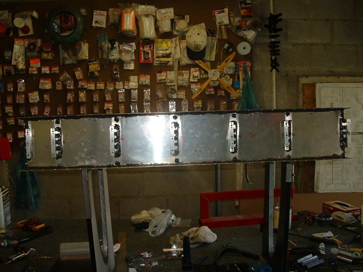
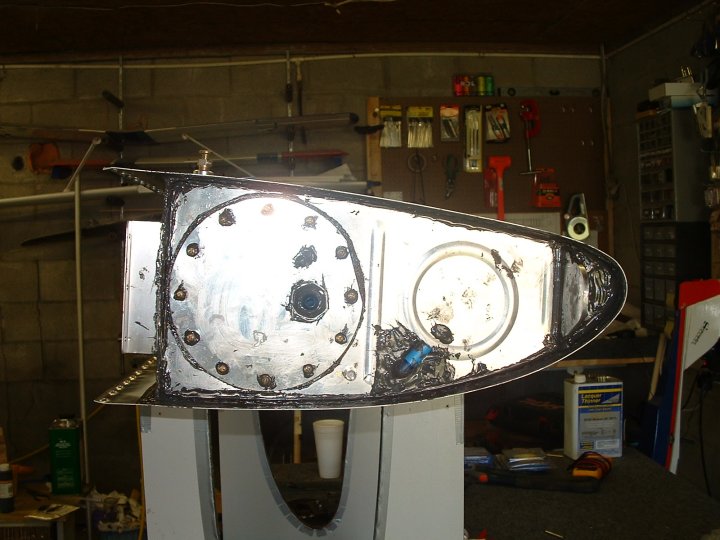
And the top side.....................with the fuel filler ring in place | ||
|
|
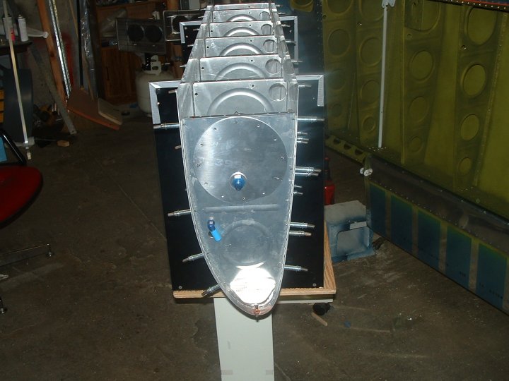
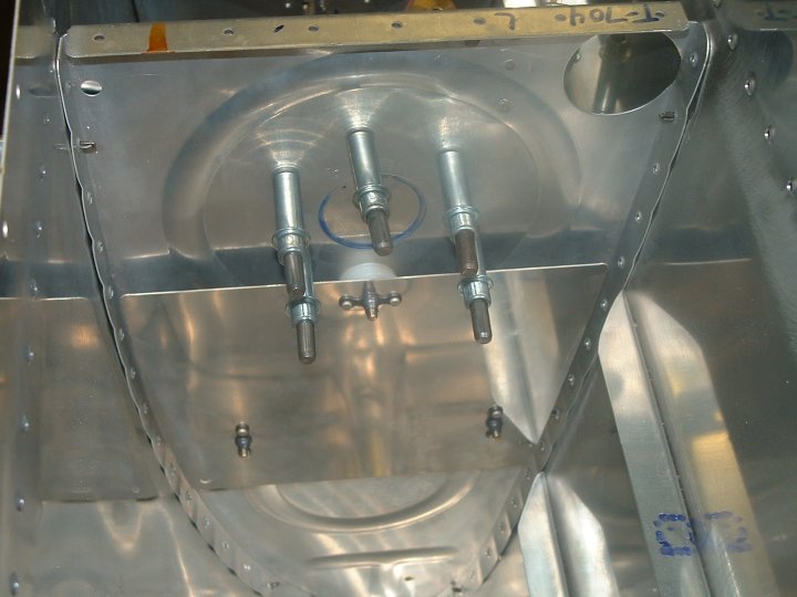
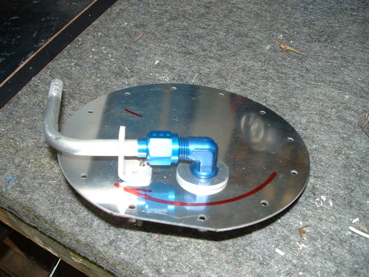
The fuel pickup mounted in the end plate of the right tank | ||
|
|
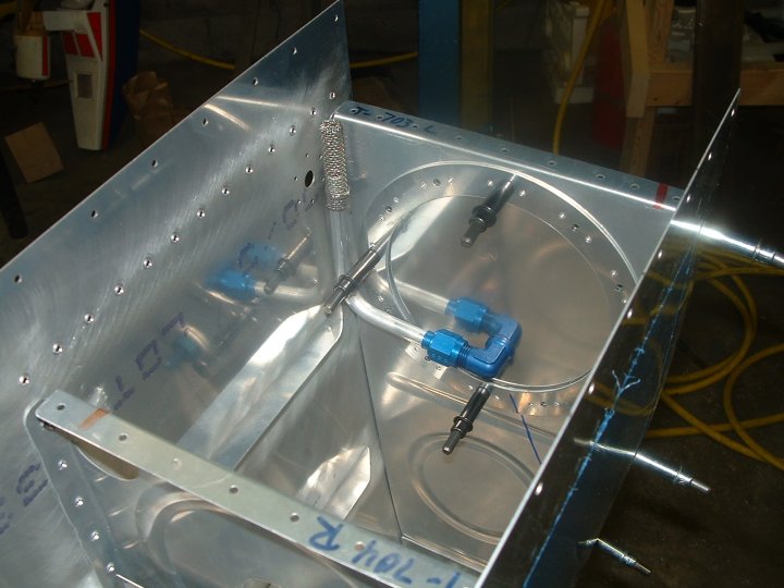
The fuel outlet tube and vent fitting on the right tank | ||
|
|
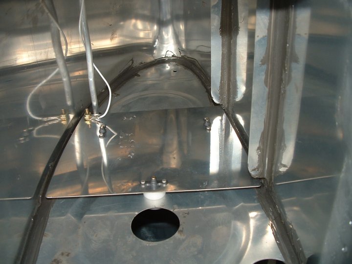
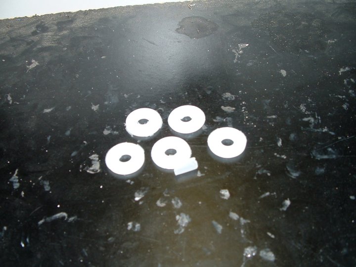
I decided to use the capacitive fuel sending units rather than the float type. Here is the outer sending unit plate all mounted to the rib with insulating washers. | ||
|
|
And the inner sending unit plate. I haven't fully understood how these things are going to work yet................I just hope they do!! | ||
|
|
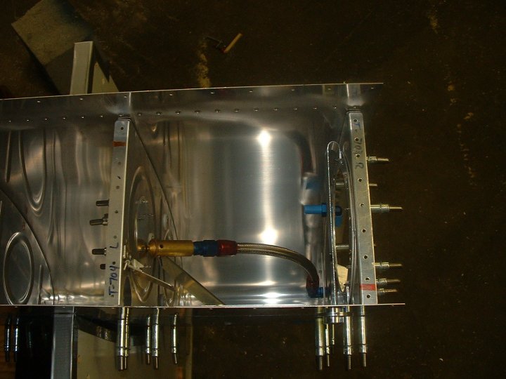
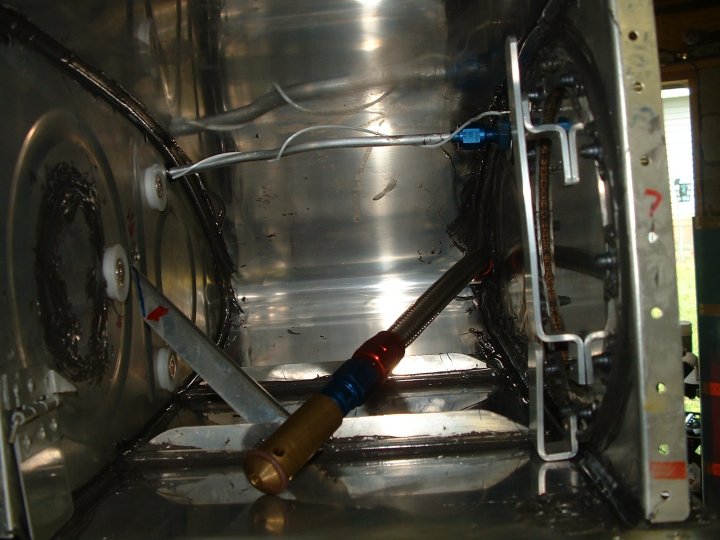
On the left tank I built it to be the inverted tank. NO........that doesn't mean it mounted on the airplane upside down!! It simply means that the fuel pickup tube is flexible so that when the airplane is upside down the tube will remain in the bottom (now top) of the tank and continue to provide the engine with the fuel that is vital to the continued operation of the pilot fan. We wouldn't want the pilot to get hot because the prop quit turning! | ||
|
|
Because the flop tube runs from the very front of the tank, you will notice the fuel outlet is in a different position than the picture of the standard tank shown above. | ||
|
|
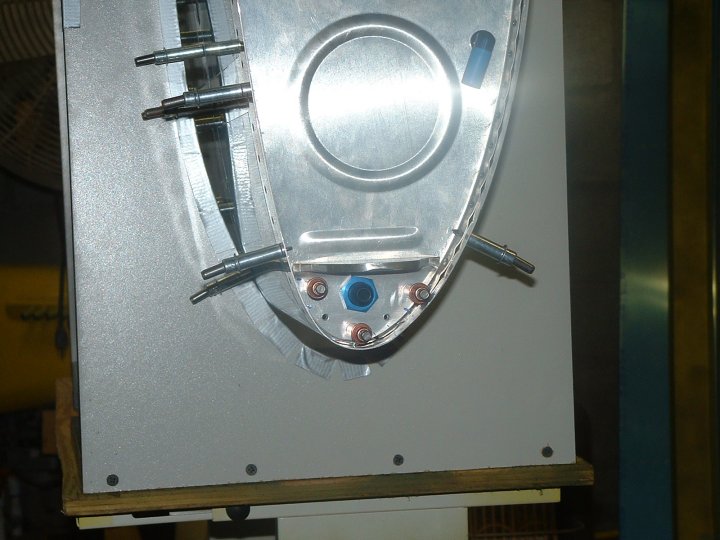
A few other modifications had to be done inside the tank as well. Guides to keep the flop tube from hanging up were fabricated as well as a small door to shut off the holes allowing fuel to escape from this bay during certain flight orientations. | ||
| So I started with the proseal and I can honestly say that this has got to be the thing that changes builders minds about finishing the project. I don't know if I have ever worked with anything quite as sticky or messy as this is.........................but it's almost over now!!! WOOHOO | |||
|
|
I've also been told that there were two ways to do this. One is to go for looks and hope all the cracks are sealed, the other is forget the looks and be sure there isn't anything left uncovered. You can tell which option I chose from the pictures! | ||
|
|
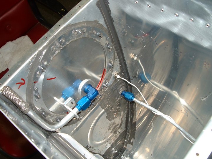
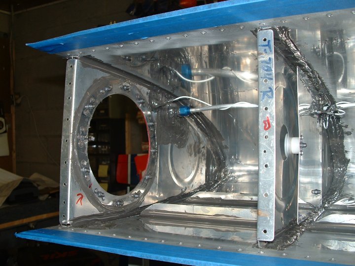
Sending unit bay all sealed up and final wires. All that is left to do is seal the wires. | ||
|
|
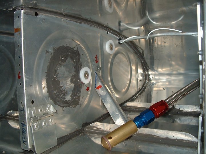
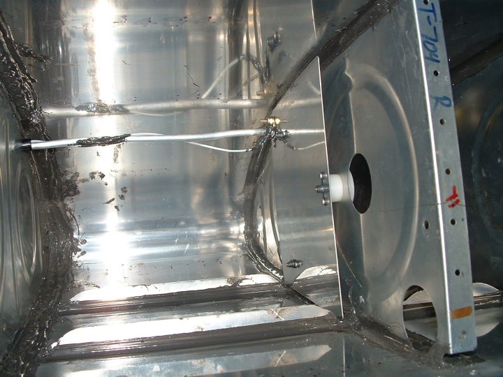
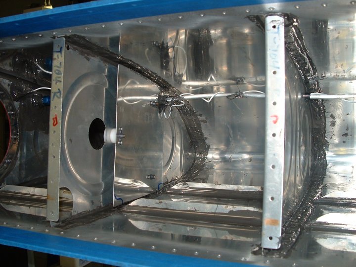
A shot of the flop tube bay all sealed up and things final mounted | ||
|
|
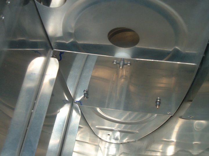
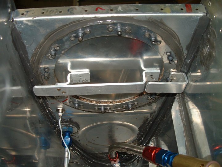
I took the advice and design from a fellow RV builder and changed the anti-hang bar in the flop tube bay even after building the one as the plans show. This design allows for un-obstructed access to the tank bay after removing the cover. It's made in two pieces to allow this. | ||
|
|
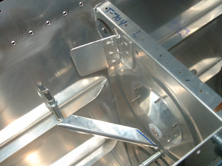
Fuel pickup in the standard tank with the anti turn bracket ready to final install. | ||
|
|
Another shot of the sending unit plate. | ||
|
|
A close shot of the access cover ready for final sealing and assembly. | ||
|
|
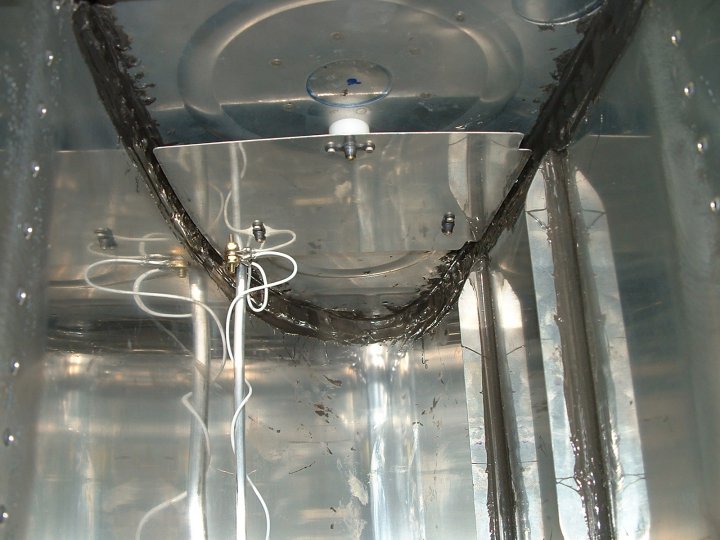
At the suggestion of a fellow RV'er, I made a modification of the anti-hang guide for the flop tube. The new guide allows total access to the flop tube bay without the guide being in the center of the access hole. When the cover is removed, the large section of the guide comes out with it. An extremely neat modification! | ||
|
|
Another shot of the above modification | ||
|
|
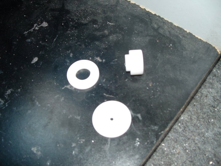
Here is yet another idea coming from someone who has been there before me. The capacitive fuel gauge sender come with a very tinker-toy nylon insulator that looks like trouble on the horizon. The originals are shown on the left with the newer improver version on the right. | ||
|
|
Everything all in place, fitted, and ready to final seal the rear baffle in place. I sure hope I didn't miss anything with that seal gook..........................the point of no easy return | ||
|
|
And it's all sealed up and ready for pressure testing! | ||
|
|
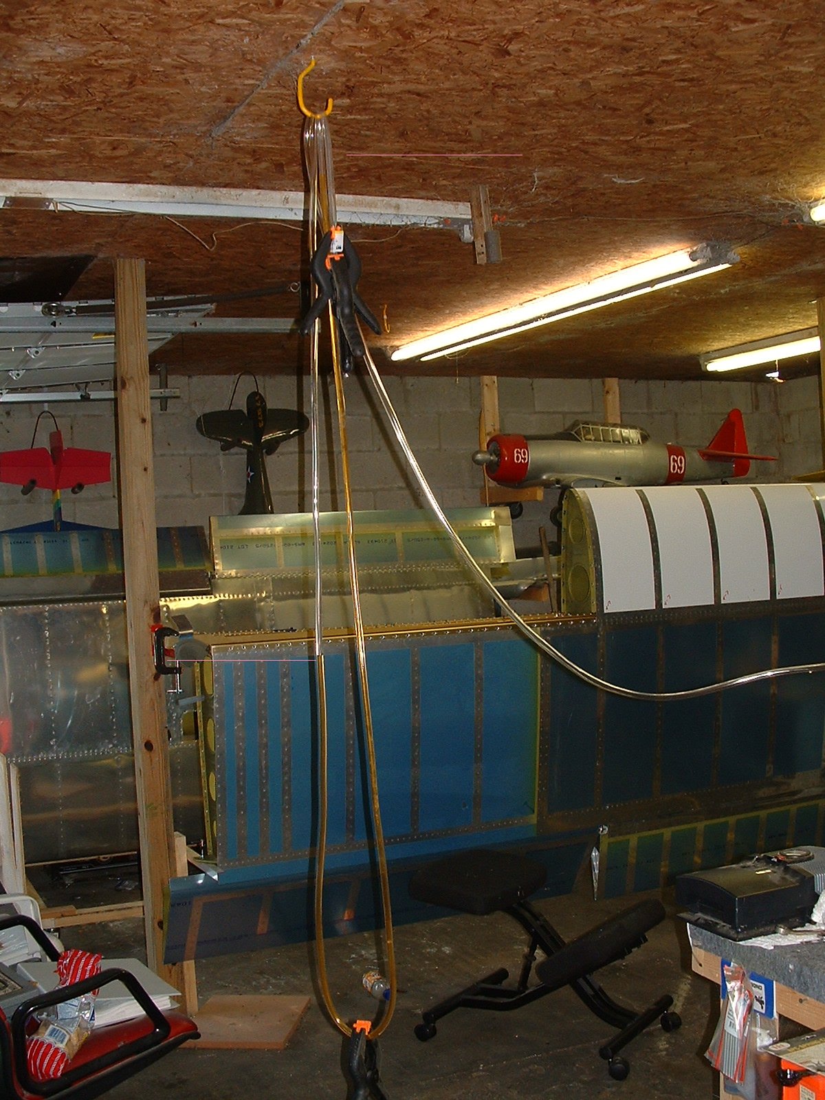
And the final test. Here is a shot of a simple pressure test being done to the tanks. Fist I cut open a balloon to wrap around the filler cap to be sure it made a gooooood seal and wouldn't leak. I then capped off the fuel supply fitting, installed the drain cock fitting, and attached a 20 foot piece of clear tubing to the vent fitting. In the clear tubing I poured some orange colored water to make it visible, looped it over a hook in the ceiling. I then drapped it down and back up over the hook leaving the water in the hanging part. With a small battery air compressor, I pressurized the tank through the drain cock to make the water in the tube lower on one side of the loop and raise on the other side as shown by the pink lines in the picture. Once this was done I marked where the water stopped and just let it set. If the level didn't change, there were no leaks. I made the right choice on not going for looks as I did not have any leaks!!!!!! | ||
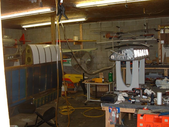
Below are just different shots taken along the way
 |
 |
|
 |
 |
 |
 |
 |
 |
 |